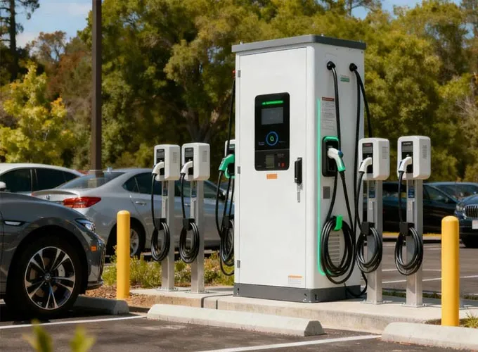
A charging-port cover moves through a defined trajectory before reaching its open, closed or latched position. A suitably installed sealed micro switch can provide an electrical indication at a chosen point in that motion. Selection starts with the exact position the vehicle needs to detect.

Define the position being detected
| Mechanism | Required reference |
|---|---|
| Outer cover or flap | The intended cover position and its striker, hinge or cam movement. |
| Connector latch | The latch's own mechanical engagement position. |
| Electronic locking unit | The locking member's required state and the associated control sequence. |
Map each required input to the mechanism that actually produces it. The contact state for a cover must be interpreted using the selected circuit, mounting position and controller logic. Confirm how the vehicle checks transitions, intermediate positions and any required diagnostic conditions.
Match the striker path and actuator travel
For a hinged cover, identify the arc followed by the striker. For a linkage or cam, record the actuator contact direction and displacement through the full movement. Compare the mechanism's tolerance stack with the switch operating position, release position and permitted overtravel.
Check that the switch changes state only at the position intended by the system design and that the actuator is not used as the mechanical end stop. Connector or wire routing should accommodate the movement and assembly process without loading the terminals.
Review the exposed installation zone
Describe the water, dust, road contamination, vibration, temperature and cleaning exposure at the mounting point. Confirm the selected housing, actuator seal, wire exit and connector arrangement against the project requirements. A family-level protection description does not establish protection for an unsealed terminal or a different assembly.
Validate the production-intent installation through repeated opening and closing, relevant environmental conditioning and electrical checks under the actual load. Keep the test conditions and final ordering code with the controlled drawing.
Prepare a cover-detection review
Send the hinge or linkage drawing, the required detected position, contact-state sequence, controller input characteristics and installation environment. Add the incumbent part number and target quantity if available. Review the EV charging application section and use the request below to keep cover detection separate from connector or lock requirements.
Ratings and dimensions depend on the exact configuration. Request the current controlled datasheet, drawing revision, and validation requirements before design approval.