
Application engineering
Micro Switch Float Detection for Dryer Overflow
Use the movement of a float to detect an abnormal condensate level in a dryer collection system. Review the float mechanism and the controller response before choosing the switch configuration.
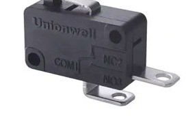
How the signal is created
Connect the mechanism
to the selection checks.
As collected water rises, a float changes position and actuates a switch. The appliance controller can use that input to identify an abnormal drainage or collection condition according to its system design.
| Review area | Information and checks |
|---|---|
| Float geometry | Float buoyancy, lever ratio, trip and release levels, overtravel and the return path when the water level drops. |
| Switch circuit | Controller input or directly switched load, contact state, voltage, current, inrush and switching frequency. |
| Moisture and contamination | Condensation, lint, detergent residue, water direction, terminal protection and the enclosure drainage path. |
| Validation | Repeated fill/drain cycles, blocked drainage, float sticking, tolerance changes and appliance fault-response tests. |
Platforms to review
Start a model-specific shortlist.
These platforms are discussion starting points. Confirm the complete part number, drawing, electrical rating and validation scope for the mechanism.
Before you commit to a configuration
Does a sealed switch solve every overflow failure?
No. A stuck float, blocked drain, wiring fault or controller problem can defeat the intended response. Validate the complete sensing mechanism and appliance fault handling. Sealing requirements must cover terminals and wiring as well as the switch body.
What defines samples, MOQ and delivery timing?
Send the mechanism requirements, target part number, sample quantity, annual forecast and target timing. Unionwell will confirm configuration availability, any tooling or validation needs, MOQ and the quotation schedule after review.
Evidence for the next design decision
Separate component data
from assembly validation.
Use the candidate's published component data to define tests for your mechanism. A component rating is not a result for every latch, connector or appliance assembly.
G5 reference
G5S05-D1P025-80AU pin-plunger example
- Example configuration: G5S05-D1P025-80AU - The example is one configuration, not every G5 or G5E variant.
- Published ENEC/CQC rating entries: 0.1 A 48 VDC; 0.1 A 125/250 VAC; 5(2.5) A 125/250 VAC - Check the exact temperature grade and approval file for the selected load.
- Published UL/cUL rating entry: 5 A 1/10 HP 125/250 VAC - Motor and resistive loads require different approval checks.
G5W11 reference
G5W11 W3 rating-code reference
- Published W3 ENEC rating entries: 10(2) A 125/250 VAC; 0.5 A 125 VDC; 0.25 A 250 VDC - Other W1/W2 configurations have different ratings.
- Protection with terminal type: IEC IP67, terminals not included - Protect exposed terminals within the equipment design.
- Protection with wire type: IEC IP67 - Confirm wire entry and end termination in the final assembly.
Define measurable acceptance criteria
- Choose the complete switch configuration and approved mechanism drawing.
- Specify cycling count, electrical load, force/travel tolerance and environmental exposure for the assembly.
- Record test equipment, conditions, sample count, results and any failures in the project validation report.
- Confirm pilot release, forecast and production timing after the results and customer approval are reviewed.
Application review
Get a shortlist for
this mechanism.
Share the movement, circuit and environment. Add drawings or test requirements to your follow-up conversation when available.