
Application engineering
Position Feedback for EV Charging Connector Locks
Review lock movement and position feedback together when selecting switching components for a charging connector or socket. The switch senses a mechanical state; the equipment controller owns the charging and fault logic.
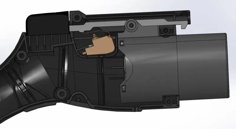
How the signal is created
Connect the mechanism
to the selection checks.
Lock-pin movement changes a feedback contact at a defined position. Motor electronic-lock assemblies and standalone feedback switches have different interfaces, so identify which part of the mechanism is being sourced.
| Review area | Information and checks |
|---|---|
| Lock architecture | DC connector or onboard AC socket, locking stroke, manual-release path, installation envelope and harness interface. |
| Feedback circuit | Normally open or normally closed state, signal voltage/current, resistor coding and the controller response to an open or short circuit. |
| Exposure | Connector water paths, cable strain, temperature, dust and the sealing boundary of the full assembly. |
| Validation | Repeated engagement/release, interrupted movement, feedback timing and the applicable equipment approval plan. |
Platforms to review
Start a model-specific shortlist.
These platforms are discussion starting points. Confirm the complete part number, drawing, electrical rating and validation scope for the mechanism.
Before you commit to a configuration
Can a feedback switch directly switch the charger high-voltage circuit?
Do not infer a power-switching rating from the charging application. The feedback circuit and the high-voltage power path are different. Select the exact switch for its specified circuit and validate the equipment separately.
What defines samples, MOQ and delivery timing?
Send the mechanism requirements, target part number, sample quantity, annual forecast and target timing. Unionwell will confirm configuration availability, any tooling or validation needs, MOQ and the quotation schedule after review.
Evidence for the next design decision
Separate component data
from assembly validation.
Use the candidate's published component data to define tests for your mechanism. A component rating is not a result for every latch, connector or appliance assembly.
G303R reference
G303R resistor-feedback configuration
- Published electrical example: 10 mA at 12 VDC - Confirm the sensing circuit and resistor code; this is not a load-switching rating.
- Operating force at pin plunger: 130 gf / 200 gf options - Actuator geometry changes the force at the mechanism.
- Circuit options: SPST-NO / SPST-NC - Confirm the required released and actuated states.
G23A reference
G23A Motor Electronic Lock for DC Charging Gun
- Rating: 12VDC.
- Insulation Resistance(at 500VDC): 100MΩ Min.
- Dielectric Strength: 500VAC (50~60Hz)
G23B reference
G23B Motor Electronic Lock for Onboard AC Charging Socket
- Rated voltage: 12VDC (pulse)
- Voltage range: 12±10% VDC.
- Idling current: <50mA
Define measurable acceptance criteria
- Choose the complete switch configuration and approved mechanism drawing.
- Specify cycling count, electrical load, force/travel tolerance and environmental exposure for the assembly.
- Record test equipment, conditions, sample count, results and any failures in the project validation report.
- Confirm pilot release, forecast and production timing after the results and customer approval are reviewed.
Application review
Get a shortlist for
this mechanism.
Share the movement, circuit and environment. Add drawings or test requirements to your follow-up conversation when available.