
Application engineering
Micro Switches for Automotive Door Latches
Convert a defined latch position into a repeatable control-system input. Start with the latch movement, sensing circuit, sealing boundary and tolerance stack, then review a suitable Unionwell configuration.
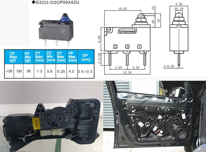
How the signal is created
Connect the mechanism
to the selection checks.
A cam or lever in the latch changes the switch state as the mechanism moves. The controller interprets that signal as part of its door-state logic; the exact states and diagnostic function depend on the vehicle design.
| Review area | Information and checks |
|---|---|
| Mechanical interface | Actuator direction, mounting datum, operating and release points, available overtravel and tolerance stack. |
| Electrical signal | Logic input or load switching, wetting current, voltage, contact arrangement and any diagnostic resistor values. |
| Environmental boundary | Water path, wire exit, condensation, vibration, shock and temperature at the installed position. |
| Validation | Door cycles, slam conditions, signal stability and electrical fault cases defined by the vehicle program. |
Platforms to review
Start a model-specific shortlist.
These platforms are discussion starting points. Confirm the complete part number, drawing, electrical rating and validation scope for the mechanism.
Before you commit to a configuration
Does a switch alone confirm that a door latch is safe?
No. Door status and diagnostic coverage depend on the complete latch, control logic, wiring and vehicle validation. A switch-series recommendation is a starting point for engineering review, not a system safety approval.
What defines samples, MOQ and delivery timing?
Send the mechanism requirements, target part number, sample quantity, annual forecast and target timing. Unionwell will confirm configuration availability, any tooling or validation needs, MOQ and the quotation schedule after review.
Evidence for the next design decision
Separate component data
from assembly validation.
Use the candidate's published component data to define tests for your mechanism. A component rating is not a result for every latch, connector or appliance assembly.
G303R reference
G303R resistor-feedback configuration
- Published electrical example: 10 mA at 12 VDC - Confirm the sensing circuit and resistor code; this is not a load-switching rating.
- Operating force at pin plunger: 130 gf / 200 gf options - Actuator geometry changes the force at the mechanism.
- Circuit options: SPST-NO / SPST-NC - Confirm the required released and actuated states.
G9 reference
G9A05-200S00A-U spherical pin-plunger example
- Example configuration: G9A05-200S00A-U - Confirm whether G9, G9A or G9B matches the mechanism.
- Published UL/cUL rating entries: 5 A 125/250 VAC; 5 A 30 VDC - Confirm load category and current controlled approval scope.
- Operating force: 200 gf maximum - This reference is for the pin-plunger example.
Define measurable acceptance criteria
- Choose the complete switch configuration and approved mechanism drawing.
- Specify cycling count, electrical load, force/travel tolerance and environmental exposure for the assembly.
- Record test equipment, conditions, sample count, results and any failures in the project validation report.
- Confirm pilot release, forecast and production timing after the results and customer approval are reviewed.
Application review
Get a shortlist for
this mechanism.
Share the movement, circuit and environment. Add drawings or test requirements to your follow-up conversation when available.